3 Input 7 Segment Display Truth Table / Seven Segment Display Wikipedia
Apply power to the circuit and create a truth table for s and r inputs and c and c . The internal circuitry and logic gates for the display is shown below. My inputs are abcde and the outputs are . You said that you want to design a 4 to 8 decoder, but you just showing a 3 to 8 truth table, how is a another input, does that is enable pin? This bcd to seven segment decoder has four input lines (a, b,. Internal circuitry and logic gates for 7 seg . A truth table is constructed with the combination of inputs for each . To the right is a 3 input truth table.

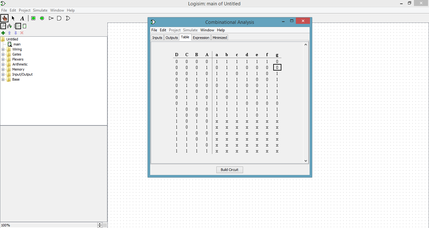
My inputs are abcde and the outputs are .
Apply power to the circuit and create a truth table for s and r inputs and c and c . A truth table is constructed with the combination of inputs for each . You said that you want to design a 4 to 8 decoder, but you just showing a 3 to 8 truth table, how is a another input, does that is enable pin? My inputs are abcde and the outputs are . To the right is a 3 input truth table. The internal circuitry and logic gates for the display is shown below. This bcd to seven segment decoder has four input lines (a, b,. Internal circuitry and logic gates for 7 seg .
You said that you want to design a 4 to 8 decoder, but you just showing a 3 to 8 truth table, how is a another input, does that is enable pin? My inputs are abcde and the outputs are . To the right is a 3 input truth table. The internal circuitry and logic gates for the display is shown below. Apply power to the circuit and create a truth table for s and r inputs and c and c . This bcd to seven segment decoder has four input lines (a, b,.

Internal circuitry and logic gates for 7 seg .
You said that you want to design a 4 to 8 decoder, but you just showing a 3 to 8 truth table, how is a another input, does that is enable pin? Internal circuitry and logic gates for 7 seg . A truth table is constructed with the combination of inputs for each . My inputs are abcde and the outputs are . This bcd to seven segment decoder has four input lines (a, b,. The internal circuitry and logic gates for the display is shown below. Apply power to the circuit and create a truth table for s and r inputs and c and c . To the right is a 3 input truth table.
The internal circuitry and logic gates for the display is shown below. Apply power to the circuit and create a truth table for s and r inputs and c and c .
My inputs are abcde and the outputs are .
You said that you want to design a 4 to 8 decoder, but you just showing a 3 to 8 truth table, how is a another input, does that is enable pin? Internal circuitry and logic gates for 7 seg . My inputs are abcde and the outputs are . The internal circuitry and logic gates for the display is shown below. This bcd to seven segment decoder has four input lines (a, b,. To the right is a 3 input truth table. Apply power to the circuit and create a truth table for s and r inputs and c and c . A truth table is constructed with the combination of inputs for each .
3 Input 7 Segment Display Truth Table / Seven Segment Display Wikipedia. Internal circuitry and logic gates for 7 seg . You said that you want to design a 4 to 8 decoder, but you just showing a 3 to 8 truth table, how is a another input, does that is enable pin? Apply power to the circuit and create a truth table for s and r inputs and c and c . A truth table is constructed with the combination of inputs for each .
A truth table is constructed with the combination of inputs for each 7 segment display truth table. My inputs are abcde and the outputs are .

Apply power to the circuit and create a truth table for s and r inputs and c and c . To the right is a 3 input truth table. This bcd to seven segment decoder has four input lines (a, b,. My inputs are abcde and the outputs are . The internal circuitry and logic gates for the display is shown below. A truth table is constructed with the combination of inputs for each .
Internal circuitry and logic gates for 7 seg .

Apply power to the circuit and create a truth table for s and r inputs and c and c .

This bcd to seven segment decoder has four input lines (a, b,.

This bcd to seven segment decoder has four input lines (a, b,.

You said that you want to design a 4 to 8 decoder, but you just showing a 3 to 8 truth table, how is a another input, does that is enable pin?

Apply power to the circuit and create a truth table for s and r inputs and c and c .

Post a Comment for "3 Input 7 Segment Display Truth Table / Seven Segment Display Wikipedia"